Ultrasonic Distance Sensor from Scratch - Transmitter
2020-06-16Using a MAX232 transceiver IC as a charge pump to drive an ultrasonic transducer
After we went over the fundamentals of the receiver, we will now go into what we need in order to transmit ultrasonic pulses. This will be much shorter than the first section, since we are esentially only (ab-)using a single component to amplify a 40kHz square wave which we generate with our MCU.
1. Theory
An ultrasonic transmitter is really just a less capable version of a speaker: Something gets swung back and forth by a changing electric field, creating waves in the medium around it. For us, that means that we need to create a 40kHz square wave. The higher the amplitude of our square wave, the more energy our speaker will transmit (and the stronger the reflection we can measure becomes, meaning we get more range). The problem is: creating square waves with a positive and negative swing and sufficient driving power usually requires quite a few components. Not ideal for something that's supposed cheap and lightweight and relatively easy to manufacture. Luckily, someone has already gone through the trouble for us and built a component that already brings most of what we need: The MAX232 is a component that is originally designed to translate RS232 voltages that can range from -15V to 15V to friendlier 0-5V TTL levels. It also packs two charge pumps that are capable of doubling the supply voltage range.
2. Circuit Design
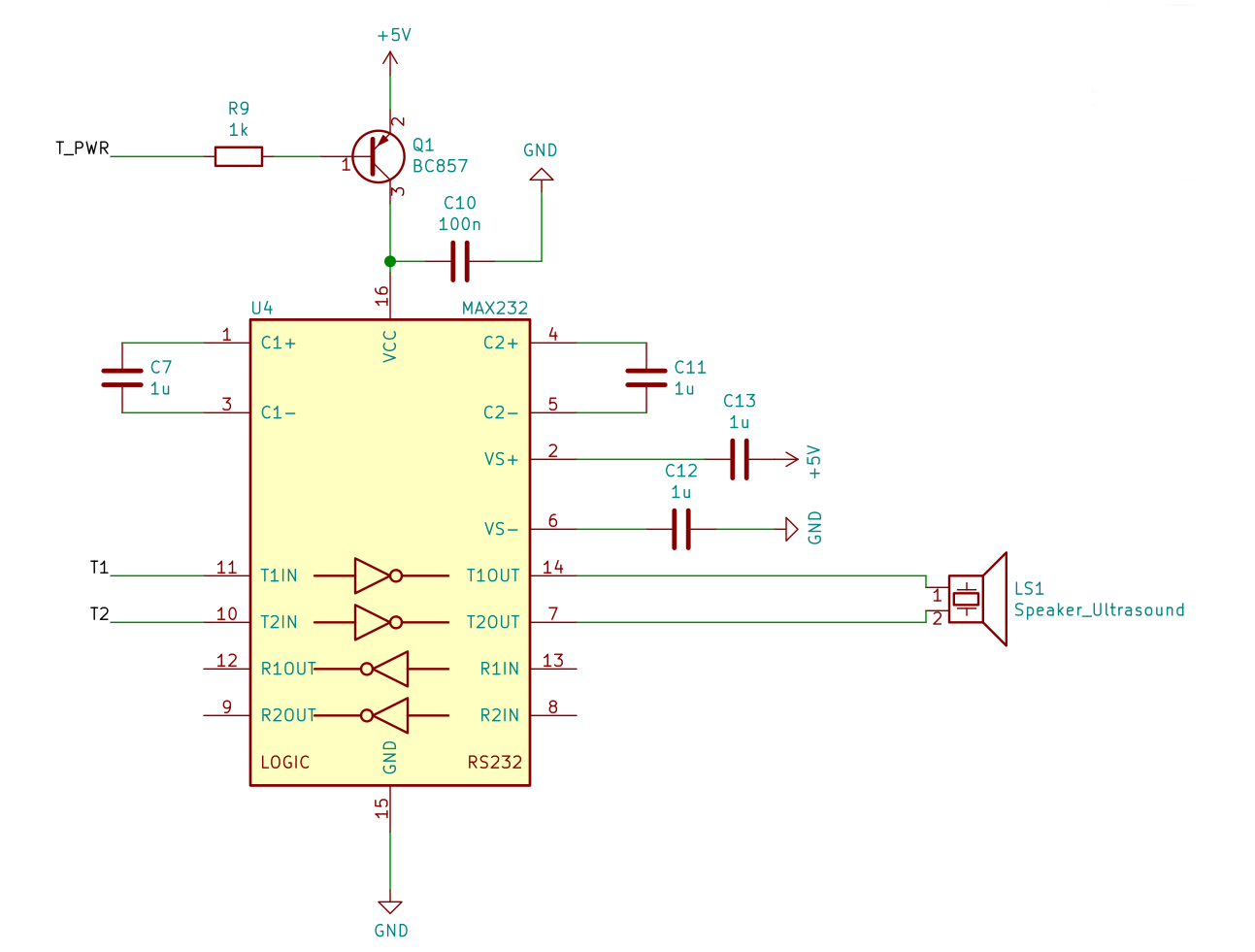
The sender circuit is almost a verbatim copy from the reference circuit found in the datasheet

Here are the individual pins and what we are using them for:
T1OUT/T2OUT: High voltage outputs that will drive our speakerT1IN/T2IN: TTL inputs that we use to control the voltage that gets applied to our speakerR1OUT/R2OUT/R1IN/R2INThese are for receiving RS232 signals. We don't need them, so we'll simply leave them unconnected.C1+/C1-/C2+/C2-/VS+/VS-: Storage capacitors for the two charge pumps. We'll simply stick with the value from the datasheet here and connect four 1uF ceramic capacitors.VCCSupply voltage. There's a PNP transistor connected in series in order to disable the MAX232 when it's not needed. This should be most of the time, since we only use it to transmit a short burst and then wait for the response. Other parts like the MAX222 come with a built-in Shutdown/Enable pin to do this, but they are more expensive and harder to source.
3. Code
Unfortunately, this is something that I still have to do...
4. Up next
After we have a working circuit for sender and receiver and can emit pulses, the only thing that is missing is some ADC code the measures the delay between emitting the pulse and receiving the peak of the reflected signal. p